


The novel approach proposed in this thesis starts from the idea of considering logic control as a recipe mainly composed by two ingredients:
- a set of basic actions.
- one or more desired sequences to coordinate actions execution. The first ingredient represents mechanisms of functionality implementation, while the second represents the control policy.
How to use GA Approach
- Identify basic actions of the process;
- Define Do-Done actions;
- Define Start-Stop actions;
- Identify the GAs by grouping actions with overlapping sets of sensors or actuators;
- Design each GA by:
- Defining its interfaces;
- Designing the actuation logics according to reference model
- Designing the internal diagnostics and quality assessment procedures (not considered in this work);
- Design the high–level policies
The First Example
This example is an adaptation of the drilling machine in processing station of FESTO manufacturing systems. We will deal with the different functionalities desired for the system in different steps; namely these functionalities are:
- To drill a workpiece using a presence sensor;
- Control duration of drillin according to a suitable policy;
- Diagnostic sensors faults;
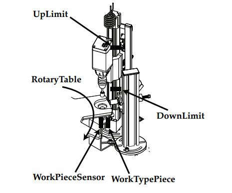
It is composed by a rotary table that feeds some workpiece to a drilling station that perform the drill operation over the workpiece. The rotary table is actuated through the command signal RotaryTable; the system is equipped with a sensor that indicates when a workpiece is in the correct position to be drilled (signal WorkPieceSensor). The electric motor that vertically moves the drilling unit has two direction of movement, decidable through command signals DrillingUP and DrillingDOWN; the combination DrillingUP=1 DrillingDown=0 causes the upward direction while the combination DrillingUO=0 DrillingDOWN=0 causes the downward direction. Two sensors indicate the up limit stop (signal LimitUP) and the down limit stop (signal LimitDown) of the drilling unit. The drilling unit is equipped with a drilling tool mounted into a spindle moved by an electric motor; the spindle has two different direction of movement, decidable through command signals DrillingRotationON and SpindleMotorDirection, namely clockwise movement can be issued through the combination of DrillingRotationON=1 and SpindleMotorDirection=1, while the anticlockwise movement can be issued through the combination of SpindleMotorON=1 and SpindleMotorDirection=0.
When a new workpiece arrives under the drilling unit, this must reach its downward position and the spindle must turn clockwise to perform the drilling operation to the workpiece. The drilling operation must continue for five seconds. After this time interval, the drilling unit must reach its upward limit while the load is expelled; during this operation the spindle must turn anticlockwise to allow the correct extraction of the drilling tool from the load. The overall process must start when the command StartProcess is active and should stop when StartProcess becomes false.
Common Solution
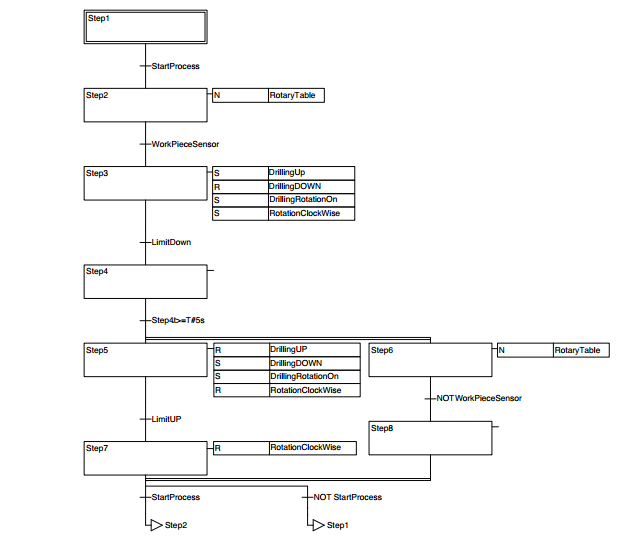
It is not hard to draw this SFC diagram according to the preceding part of the text.But the designed solution lacks of separation between logic policies and actuation mechanisms, reflecting into a lack of re-usability and modularity; this directly affect the readability of the software but also (and especially) the possibility to make some changes quickly and easily as it can be noted considering the following modifications to the plant and policies.
Now, let's consider the following modifications to the plant and policies.
- Suppose that the considered system is equipped with a presence sensor which cannot be considered as ideal: signal
WorkPieceSensorbecomes true as soon as the workpiece reaches the sensor but this position is not correctly centered below the drilling unit; the belt must therefore move for a given time interval that depends on its actual speed and the load dimensions in order to bring the load in the correct position. - Suppose that the system can manage two different types of workpiece and, depending by the kind of workpiece (indicated by signal
WorkPieceTypeSensor) the drilling operation must be three or five seconds long (i.e. the reference for the temperature control changes according to the actual product).
Note that the modification (1) is related to an action sensor (generally to an actuation mechanism) while modification (2) is referred to a policy change but this characteristics are not clearly distinguishable in the SFC diagram.
Detail discuss will not be summarized here. You can go to the original book to read if you are interested in it.
Use The Generalized Actuator approach
(1) Identify basic actions of the process
For the considered system the basic actions to perform are
- move the workpiece in drilling position, indicated as
Positioning; - expel the drilled workpiece,indicated as
Expulsion; - move the drill unit upward, indicated as
DrillGoUp; - move the ram downward, indicated as
DrillGoDown; - control the spindle rotation, indicated as
SpindleControl.
(2)Define Do-Done and Start-Stop actions
From the considered example, it is immediate to note that there exist two different kinds of actions and, consequently, of GAs; there are actions which structurally terminate after a finite time (e.g. action Positioning implies moving the belt until the workpiece reaches the drilling position), while there are others which, in principle, could continue for an infinite time and whose termination has to be decided “externally”(e.g. action SpindleControl).
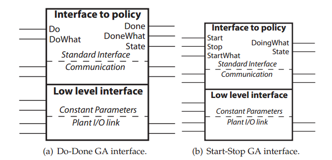
The GAs associated to the first kind of actions are denominated Do-Done GA. They are characterized by a input signal Do used to command the starting of an action, an input signal DoWhat to specify what kind of action has to be performed (if more than one is available) and an output signal Done to signal when the action has terminated successfully.
Differently, the GAs associated to the second kind of actions are enominated Start-Stop GA. Their characteristic I/O signals are the input Start to command the beginning of an action, defined by the input StartWhat, and the input command Stop to stop the action.
(3)Identify the GAs by grouping actions with overlapping sets of sensors or actuators
Looking for common equipment used in different actions, leads to group them in three GAs respectively devoted to the drilling workpiece, move the drill unit and control spindle rotation control.
WorkPieceMotion, a Do-Done GA that is devoted to workpiece positioning;DrillMotion, a Do-Done GA that is aimed at moving the drill unit;Spindle, a Start-Stop GA that is aimed at controlling the spindle rotation of drilling.
(4)Design GAs
Defining its interfaces
- Interface to policy: this section represents the input/output section between the GA and the supervision policy. It can be further decomposed in two subsections separating the standard communications between the GA and the policy and all the case dependent communications.
- Standard interface: embeds all command inputs for the GA and the outputs that communicate the actual state of the GA and the task that it is accomplishing. More in details the Do-Done GA will receive as command the Do signal to start operations and the DoWhat signal to specify the desired action, while the Start-Stop GA will be commanded through inputs Start to start operations and Stop to conclude operations, and through signal StartWhat to define the required action. In both cases input signals Alarm, AlarmType can be used to communicate to the GA the occurrence of an external anomalous situation. The outputs of this section are, for the Do-Done GA, the Done signal by which the GA communicate that the task has been performed and the DoneWhat signal by which the terminated task is specified; the Start-Stop GA outputs are the signal DoingWhat representing the task that the GA is performing. In both kind of GAs, a State signal communicate the actual state in which the GA is evolving.
- **Communications: **represents all the non standard communications between the policy and the GA, as the results of sensor readings filtering(e.g. the
WorkPieceTypeSensorsignals inWorkPieceMotorGA that distinguish between two different kind of workpiece filtering the sensor readingsWorkPieceTypeSensor.)
- Low level interface: this section contain all the interfaces with the low level world; even this section can be further decomposed in two sub sections considering the constant parameters used by the GA separated from the physical interconnection with the plant.
- Constant parameters: contains all the inputs by which it is possible to give a constant value to characteristic parameters of the GA (e.g. in
WorkPieceMotionGA the in putPositioningDelayTimeby which define the time interval between the activating instant for sensorWorkPieceSensorand the instant in which the workpiece reaches the drilling position. - Plant I/O link: is the real interface with the plant and contains as inputs all the links to sensors and as outputs the links to actuators. In this way the physical connection between the GA and the plant is completely hidden to the high level control policy.
Designing the actuation logics according to reference model
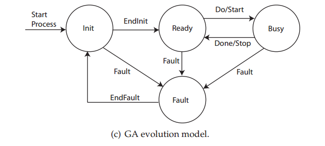
Init: this state is the initial one and becomes active as soon as the GA is activated (usually at the beginning of operations). It represents the state in which initialization actions are performed; the GA moves out from this state when a signal EndInit communicates that the initialization operations are concluded forcing the GA to move in Ready state.
Ready: in this state the GA is ready to perform the desired operation and is waiting for the Do or Start command to move to Busy state.
Busy: after the command issued by the policy the GA starts performing its required task communicating with the high level policy information on the accomplishment of the function(e.g. information on the quality of the operations). The GA remains into this state until the task is finished and the signal Done is raised (Do–Done GA) or until the Stop signal(Start–Stop GA) is issued by the policy. In these cases the GA moves back to state Ready.
Fault: from any state a signal Fault (used to communicate some anomalies) can force the GA to move into a Fault state in which some counteractions are taken. Note that the Fault signal can be both due to external commands (e.g. an alarm issued by an external operator), to internal diagnostics or to wrong logic operations. When the alarm situation is concluded (signal EndFault) the GA returns in the Init state to be reinitialized.
Comments | NOTHING